 Front-page It
 Sitemap
 »
CNC Machines for Steel Structure
»
TSWZ1000/TSWZ1250 CNC H Beam Drilling Line
»
CNC Machines for Steel Structure
»
TSWZ1000/TSWZ1250 CNC H Beam Drilling Line
TSWZ1000/TSWZ1250 CNC H Beam Drilling Line
2016-6-16 16:09:15
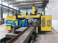
Applicable Industry:
Used for the drilling processing of H-shape steel, box beam and channel steel of steel structure, bridge, three dimensional garage and petrol platform industries.
Main description:
Ø Work-piece: H U beams
Ø Functions: Drilling, Marking(Optional unit )
Ø Quantity of drilling head: Three(Top, Left and Right)
Ø Feeding mode: Automatic NC feeding carriage --- high feeding speed ,high precision
Technical Parameters :
|
Model |
TSWZ1000 |
TSWZ1250 | ||||
|
Workpiece size |
(mm) H-beams Max. (web height×flange width) |
Max. |
1000x500 |
1250x600 | ||
|
Min. |
150x75 | |||||
|
(mm) Length |
Auto feeding |
≥3000 | ||||
|
Manual feeding |
≥690 | |||||
|
Thickness of web & flange (mm) |
80 | |||||
|
Drill dia. (mm) |
Vertical drilling |
Φ12~Φ33.5 | ||||
|
Horizontal drilling |
Φ12~Φ26.5 | |||||
|
Spindles |
No. of spindle |
One spindle on each of three sides (top,left,right) Total: 3 spindles | ||||
|
Rotation speed (stepless speed adjustment) (rpm) |
180~650 | |||||
|
Spindle motor power(KW) |
3x4 kW | |||||
|
Max. feeding stroke (mm) |
Left,Right:140 Vertical: 325 | |||||
|
(mm/min) Feeding speed |
20~300 | |||||
|
Movement of left/right spindle(mm) |
In the direction of workpiece length::520 | |||||
|
Above vertical base-level:30~470 |
Above vertical base-level:30~570 | |||||
|
Movement of top spindle (mm) |
In the direction of workpiece length:520 | |||||
|
Beyond horiizontal base-level:45~910 |
Beyond horiizontal base-level:45~1160 | |||||
|
Marking |
No. of characters |
36 characters | ||||
|
Character size(mm) |
Φ10 | |||||
|
Overall dimensions(L*W*H)(mm) |
4550x3050x3520 |
4800x3050x3520 | ||||
|
Total power (kW) |
34 | |||||
|
Machine weight (kg) |
Appr.7000 |
Appr.8000 | ||||
Product Feature:
1. Frame made of sturdy electro-welded and normalized Plates and Square Beams. The structure with roller guides on which the sliders supporting the three spindles guarantees the total moving stability, and ensures the working precision;
2. Three drilling spindles mounted on individual moving platform can equip with carbide drills. The spindles’ feeding and feedback (for exact spindle positioning) is done through 3 sets of powerful hydraulic cylinders or servo motors.
3. The sensor system automatically calculates the centerline of the beam. This permits flanges holes to be accurately positioned at given dimensions above or below the web centerline, or web holes to be located from a centerline reference.
4. The control system is a Computer based with PLC and modules controlled system. The computer facilitates the operator to design, revise, and transmitting program, or manually makes up the program. The numerical control like, PLC, modules, servos, etc. are all developed by MITSUBISHI to facilitate program creation and provide appreciable operational savings.
5. This machine can read AUTOCAD drawings and lofting software files automatically, such as DXF, NC1.
6. Equipped with automatic lubrication system and air conditioner for electric cabinet.
7. Equipped with automatic feeding systems, which will clamp and feed material into machine automatically.